2026/01/19
Results since previous meeting
- Improved the project proposal based on the feedback, and put it on this website there
- Looked in more details into the definitions of footprint and roofprint
Material for discussion
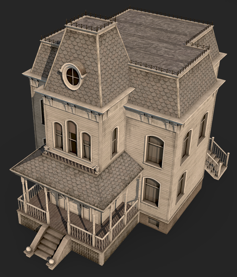
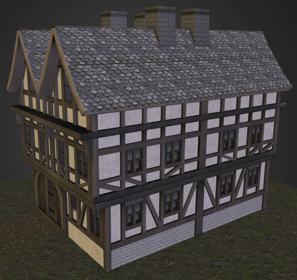
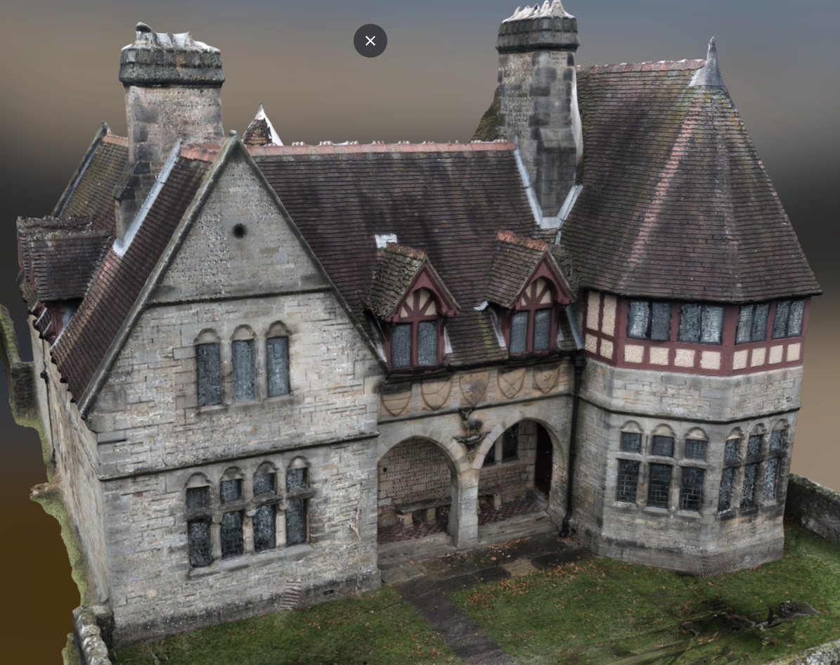
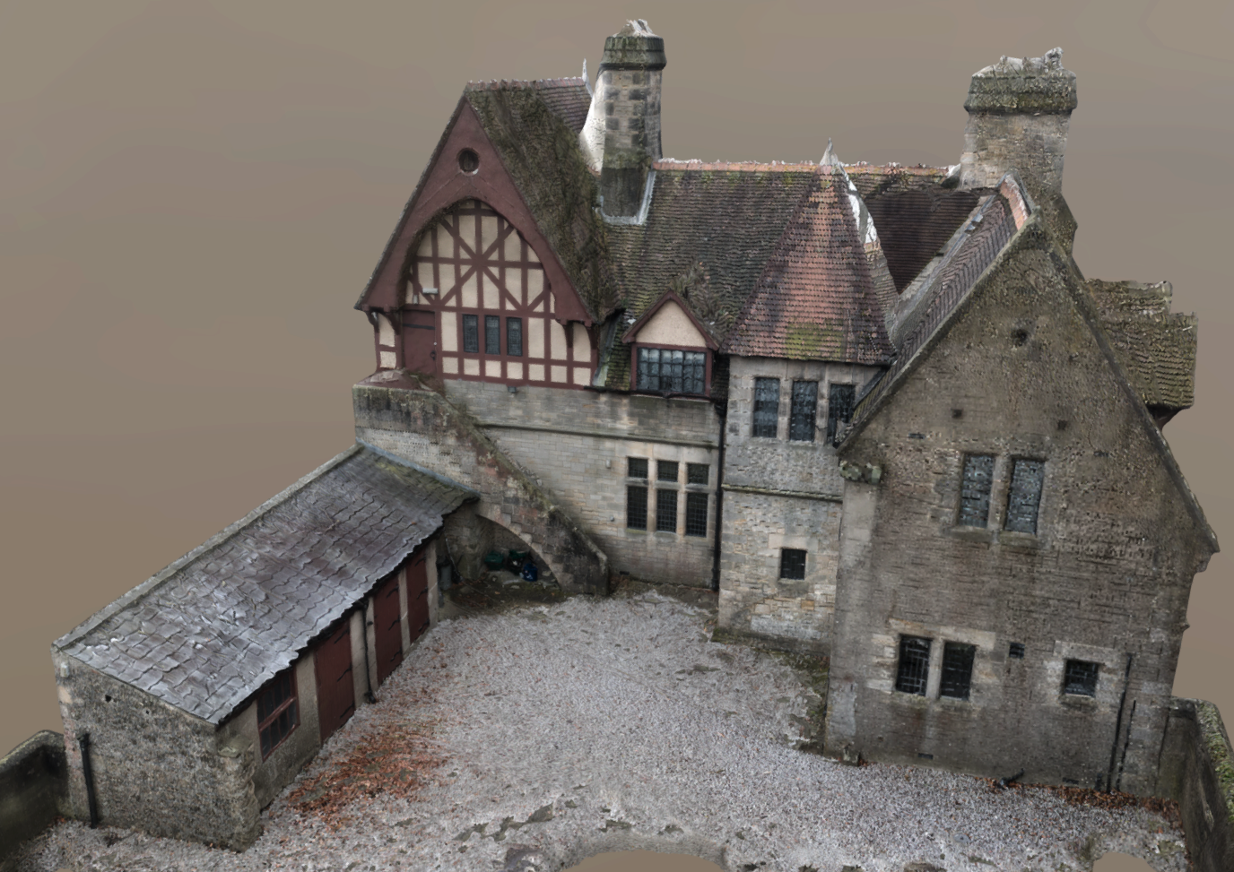
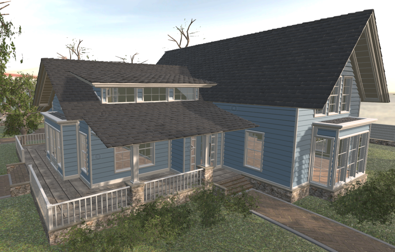
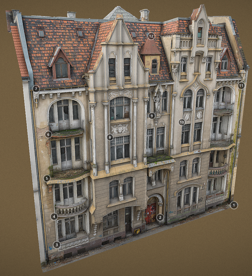
How could we define the footprints and roofprints more precisely? Here are some examples of buildings where defining them is not easy:
In BD TOPO, the definitions are the following.
For the buildings coming from the BD PARCELLAIRE:
La forme du contour est prise au sol. Le polygone est aplati c’est-à-dire que l’on affecte à chaque point du bâtiment unifié la même altitude toit (comme une « boîte à chaussures »).
Translated to English:
The shape of the outline is taken from the ground. The polygon is flattened, i.e. each point of the unified building is assigned the same roof height (like a ‘shoebox’).
For the buildings derived from photogrammetric restitution processes or captured on orthophotography:
Contour extérieur du bâtiment tel qu’il apparaît vu d’avion (le plus souvent, ce contour correspond à celui du toit); altitude correspondant à ce contour (généralement l’altitude des gouttières). Seules les cours intérieures de plus de 10 m de large sont représentées par un trou dans la surface bâtie.
Translated to English:
Outer contour of the building as seen from the air (in most cases, this contour corresponds to the roof); altitude corresponding to this contour (usually the height of the gutters). Only inner courtyards wider than 10 m are represented by a hole in the built-up area.
The Merged Approved Documents (from UK Building Regulations):
Definition from Approved Document B Volume 2, 2019 edition, page 112
The footprint of the building is the maximum aggregate plan perimeter found by the vertical projection of any overhanging storey onto a ground storey
Approved Document O, 2021 edition, page 6 mentions that to provide shading in “high risk location”, one solution is using
Overhangs with 50 degrees altitude cut-off on due south-facing façades only
INSPIRE D2.8.III.2 Data Specification on Buildings – Technical Guidelines has these examples:
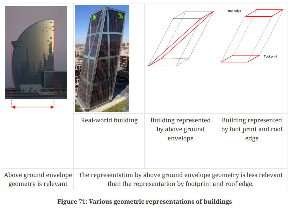
Example of building footprint and roofprint This page from Law Insider gathers definitions of building footprints, with the second one being quite detailed:
Building footprint means the horizontal area as seen in plan, measured from outside of all exterior walls and supporting columns. It includes dwellings and any area of attached garage that exceeds 200 square feet. It does not include detached garages or carports; accessory structures; trellises; patios; areas of porch, deck, and balcony less than 30 inches from finished grade; cantilevered covers, porches or projections; or ramps and stairways required for access.
An other different but interesting definition is:
Building footprint means the two-dimensional configuration of an existing building’s perimeter boundaries as measured on a horizontal plane at ground level.
or simply:
Building footprint means the outline of a building, as measured around its foundation.
These two articles here and there explain that roof overhangs server mainly three purposes:
- Protects materials against rain, snow and sunlight
- Protects materials against UVs
- Prevents overheating in summer
The first one also provides a simple way to compute the roof overhang to protect from humidity or sun.
Discussion
- A1 presentation: 15 min to Hugo, Ravi and Bruno. This doesn’t have to be formal but rather to show that I understand the topic, that it is well-defined, that I know how I am going to tackle it and have expectations about the method and the difficulties. This can be seen more as vulgarization and training for the subsequent presentations.
- The definition of the footprints and roofprints is indeed a difficult topic, especially because most buildings are similar but there will always be exceptions that will break some definitions. For this reason, since the main goal in my case is to be able to add details to some of the buildings with roof overhangs, my definition of footprints and roofprints should be coherent with the way the buildings should be modelled based on them. More specifically, the idea behind footprints is that they can be extruded vertically up to the roof, and in combination with the roofprint and roof planes, we can get an LoD 2.3 model of the building. Therefore, I should define footprints as the vertical projection of the main façades of the building. The idea of main façade still needs to be refined and specifically defined, but this captures the idea of what I hope to be able to achieve with the planned methodology.
- Regarding the lack of ground-truths, we discussed how I could generate a fake LoD 2.3 dataset from the LoD 2.2 dataset of the 3DBAG. Then, by simulating a LiDAR point cloud on this data, I would get a full dataset with ground-truths to evaluate the method. This would already be biased because the buildings would be much simpler and closer to the model that real buildings, but this is still interesting.